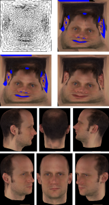
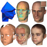
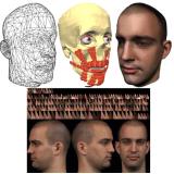
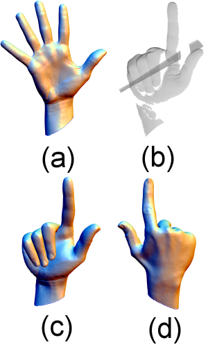
Research Projects (Publications)

Nihongo ha koko (In Japanese)


Note

There are ``Easy abstract'' in this page. These abstracts are more intuitive but less technically sound. These are for easy to catch the articles. Then, there is also some dangerousness of misunderstanding in them. So, when you are interested in one of the articles, please see the paper also.


Hand
Woman

(a) Input template
(b) Range scan data
(c) Fit result front
(d) result backside (Note, backside had no scan.)
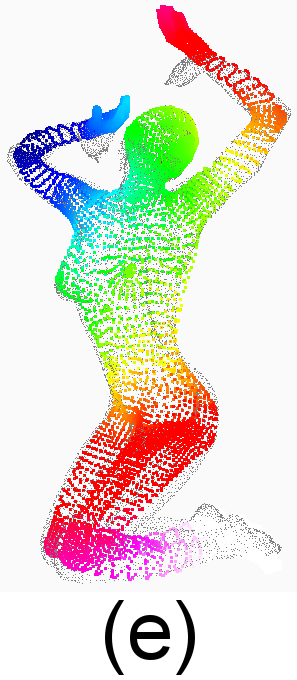
(e) Woman fit result.
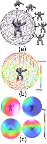
Color code shows approximated geodesic distance from a marker on the right elbow.

Template Deformation for Point Cloud Fitting

Carsten Stoll, Zachi Karni, Christian Roessl, Hitoshi Yamauchi and Hans-Peter Seidel, ``Template Deformation for Point-Cloud Fitting,'' Proc. IEEE/Eurographics Symposium on Point-Based Graphics 2006, pp.27-35

Abstract: The reconstruction of high-quality surface meshes from measured data is a vital stage in digital shape processing. We present a new approach to this problem that deforms a template surface to fit a given point cloud. Our method takes a template mesh and a point cloud as input, the latter typically shows missing parts and measurement noise. The deformation process is initially guided by user specified correspondences between template and data, then during iterative fitting new correspondences are established. This approach is based on a Laplacian setting for the template without need of any additional meshing of the data or cross-parameterization. The reconstructed surface ts to the point cloud while it inherits shape properties and topology of the template. We demonstrate the effectiveness of the approach for several point data sets from different sources.


Easy abstract:

Range scanned data usually has noise and holes. It is not so easy to reconstruct a complete mesh from such scanned data. Sometimes you can not scan some part of the object. For example, the hand model has only front side scan in the Figure (b). But non-scanned backside part is inherited from the template model and the scanned part is fit to the data. This makes complete hand model (Figure (a)-(d)). Our method is first considered as human and animals posing. But then we find this method is more general and can be apply to semantically similar objects. (Here, semantically similar is a tricky word. Like quadruped animals are somehow similar. A notebook computer and a penguin are, I may say, not semantically similar, but we can discuss as they have same topology or something.)

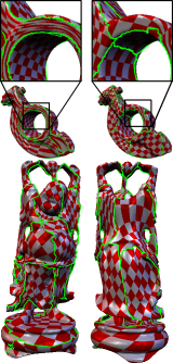
Laplacian mesh deformation is basically not rotational invariant (we need some definitions and discussions what does it really means, if you want to know, please look at the papers, e.g., Olga Sorkine's EG2005 tutorial). Our approach approximate the local frame via the same Laplacian matrix with interpolation represented by quaternion (We use the method of EG2005 Zayer et. al). Our contribution is introducing scaling and local frame rotation, and fitting with near points search. Without them, problems of self intersection and candy lapping easily break the models.

We use the same Laplacian matrix again and again: to deform the mesh, to interpolate quaternion, and to interpolate scale of the mesh (not measure the scale part, the measure part is done with Dijkstra algorithm). So, the foundation of this method is this Laplacian matrix and you can find this method is so versatile. We did not say why we use the same foundation only, but we think mathematically this is beautiful and somehow we try to keep that. In our research, we apply other different methods to improve this (e.g., multi-resolution approach, random sampling, and etc.), however, our proposed method is still better in most of the case as long as we know. Of course, our method is the simplest. Therefore, our implementation becomes simpler.


ViewSel

(a) View sampling, use 162 views.
(b) View similarity measure and forming a spherical graph.
(c) View saliency measure.

Towards Stable and Salient Multi-View Representation of 3D Shapes

Hitoshi Yamauchi, Waqar Saleem, Shin Yoshizawa, Zachi Karni, Alexander Belyaev and Hans-Peter Seidel, `` Towards Stable and Salient Multi-View Representation of 3D Shapes,'' In: IEEE International Conference on Shape Modeling and Applications 2006 (SMI2006), Matsushima, JAPAN, IEEE, Los Alamitos, 2006, pp.265-270

Additional materials:

Abstract: An approach to automatically select stable and salient representative views of a given 3D object is proposed. Initially, a set of viewpoints are uniformly sampled along the surface of a bounding sphere. The sampled viewpoints are connected to their closest points to form a spherical graph in which each edge is weighted by a similarity measure between the two views from its incident vertices. Partitions of similar views are obtained using a graph partitioning procedure and their ``centroids'' are considered to be their representative views. Finally, the views are ranked based on a saliency measure to form the object's representative views. This leads to a compact, human-oriented 2D description of a 3D object, and as such, is useful both for traditional applications like presentation and analysis of 3D shapes, and for emerging ones like indexing and retrieval in large shape repositories.


Easy abstract:

Given an 3D object as an input, how can we see the object? Which direction is more informative? This is the question of this paper to be answered in some way. Applications are, for example, 3D model thumbnail generator, normalized view generator of 3D model retrieval, and so on.

People working around object recognition usually said, one view is not enough for object recognition. We follow this idea. Then our system proposes a few candidate views and sort these views according to a criterion.

Our approach is generate sample views (162 views, Figure (a)) and first filter the unnecessary views using image comparison method. Then, sort these candidates according to perceptional measure criterion.

First stage (Filter out unnecessary views, find stable views): The idea of filtering is if the images are similar with different views one of them is not necessary. First we compute the image similarity by comparison with Zernike moments and form a spherical graph (Figure (b)). Then, graph cut gives us partition of the views. In one partition, the views are more or less similar, then only one view is necessary. Now we have small number of view candidates. In this paper, we use eight candidate views out of 162 views.

Second stage (Sort the candidates according to Saliency, find salient views): Now we have small number of candidates. To order/sort them, we use saliency measure (Itti et al. and Lee et al.) (Figure (c)). This is a perceptional criterion.


PG2005MSDGC
Top Left: textured MCGIM
segmented model.
Top Right: textured t-flooding
segmented model.
Bottom : textured t-flooding
segmented model (Happy).

Mesh Segmentation Driven by Gaussian Curvature

Hitoshi Yamauchi, Stefan Gumhold, Rhaleb Zayer and Hans-Peter Seidel, ``Mesh Segmentation Driven by Gaussian Curvature,'' Pacific Graphics 2005, Macao, China, 2005, Oct.10-12, Visual Computer, Vol.21, No.8-10, pp. 649-658, http://dx.doi.org/10.1007/s00371-005-0319-x

Additional materials:

Abstract: Mesh parameterization is a fundamental problem in computer graphics as it allows for texture mapping and facilitates a lot of mesh processing tasks. Although there exists a variety of good parameterization methods for meshes that are topologically equivalent to a disc, the segmentation into nicely parameterizable charts of higher genus meshes has been studied less. In this paper we propose a new segmentation method for the generation of charts that can be flattened efficiently. The integrated Gaussian curvature is used to measure the of a chart and a robust and simple scheme is proposed to integrate the Gaussian curvature. The segmentation approach evenly distributes Gaussian curvature over the charts and automatically ensures disc-like topology of each chart. For numerical stability, we use area on the Gauss map to represent Gaussian curvature. Resulting parameterization shows that charts generated in this way have less distortion compared to charts generated by other methods.


Easy abstract:

Here we want to segment a mesh for Texture mapping (parameterization).

To keep the parameterization distortion low, the segmented patches should be developable as possible. Developability can be measured by Gaussian curvature. Therefore, if all patches have zero Gaussian curvature, it is done. This is possible if we dissolve the mesh to all component, e.g., triangle by triangle or triangle strips. However, this is not suitable for texture mapping. Because if we dissolve triangles, boundaries of triangle have artifact. We would like to minimize both of the number of patches and amount of absolute value of Gaussian curvature.

So, the segmentation strategy is to distribute Gaussian curvature over the patches and also cut the high Gaussian curvature part. Then we may get the equally low distorted patches after parameterization.

In this paper, we use Gauss area (area on Gauss map) instead of Gaussian curvature to capture developability. For segmentation, we do not need Gaussian curvature itself, but we need some developability criterion which is robust and simple to compute, reflects Gaussian curvature properties. Gauss area satisfies these properties.

Once we get the developability measurement by Gauss area, we distribute Gauss area over the patches. We develop an algorithm called t-flooding. t-flooding stands for time parameterized flooding. We know the total Gauss area. If the growing takes time t for n patches, each patch should have t/n Gauss area at the end of segmentation. This gives us the growing speed of each patch. The algorithm trace this growing speed and all patches tend to grow the same speed. As a result, all patches should have the same Gauss area, because it grows the same speed.


FSMeshSeg
Top: Without feature
enhancement segmentation.
Bottom : With feature
enhancement segmentation.

Feature Sensitive Mesh Segmentation with Mean Shift

Hitoshi Yamauchi, Seungyong Lee, Yunjin Lee, Yutaka Ohtake, Alexander Belyaev and Hans-Peter Seidel, ``Feature Sensitive Mesh Segmentation with Mean Shift,'' In Shape Modeling International 2005, Cambridge, MA, USA, IEEE, Los Alamitos, 2005, 236-243

Additional materials:

Abstract: Feature sensitive mesh segmentation is important for many computer graphics and geometric modeling applications. In this paper, we develop a mesh segmentation method which is capable of producing high-quality shape partitioning. It respects fine shape features and works well on various types of shapes, including natural shapes and mechanical parts. The method combines a procedure for clustering mesh normals with a modification of the mesh chartification technique in [23]. For clustering of mesh normals, we adopt Mean Shift, a powerful general purpose technique for clustering scattered data. We demonstrate advantages of our method by comparing it with two state-of-the-art mesh segmentation techniques.


Easy abstract:

Here we want to segment a mesh. There is one well accepted hypothesis which is called `minima rule' from psychology area. This is a hypothesis that human recognize segments of object from high normal variation (especially concave). We are convinced this hypothesis `normal variation is important for human cognition.' We define features stay such high normal variation part.

We have defined our problem. The next task is how can we interpret this hypothesis for segmentation as a mathematical problem. Some methods based on these hypothesis used curvature, but curvature is a bit tricky to calculate with stable (numerically) and it is also hard to get some continuous line for segmentation with curvature calculation. Especially noise is problem which is always observed in a scanned mesh.

To treat features and noise, some used morphology operation, others used diffusion process, and the others used distance function with weight coefficient. One other question is the distance function usually does not care anisotropy even it cares features like dihedral angle, and features are usually not isotropic.

Our answer of this problem is simple. First we analyze the features and enhance it with anisotropical kernel density estimation method, called Mean Shift. Then, we can use feature sensitive method. Feature sensitive usually means also sensitive to noise. However, since we have already denoised and enhanced features, denoising term is not necessary anymore. Usual methods need a weight parameter (or sometimes parameters) for balancing denoise and feature sensitive effect, since noise and features are difficult to separate. But we do not want to do this in segmentation. This makes users easier to select a parameter, since the feature analysis and segmentation processes are separated.

The feature analysis is performed in 6-dimensional space (geometry position + normal). Then, segmentation takes care of the feature space and mesh connectivity in this method.


Textures Revisited Textures Revisited Numbers
1. Parameterization
2. Combination (Alpha blending)
3. Combination (Multi-res. Spline)
4. Automatic Restoration
(2.and 3.'s blue pixels)
5. Result of a Textured Model

Textures Revisited (Project page)

Hitoshi Yamauchi, Hendrik P.A. Lensch, Jörg Haber and Hans-Peter Seidel, The Visual Computer, 21(4), pp.217-241, ISBN 0178-2789, ISSN: 0178-2789 (Paper) 1432-8726 (Online), DOI 10.1007/s00371-005-0283-5, Springer, Heidelberg, May, 2005

Abstract: We describe texture generation methods for complex objects. Recent 3D scanning devices and high-resolution cameras can capture complex geometry of an object and provide high-resolution images. However, generating a textured model from this input data is still a difficult problem.

This task is divided into three sub-problems: parameterization, texture combination, and texture restoration. A low distortion parameterization method is presented, which minimizes geometry stretch energy. Photographs of the object taken from multiple viewpoints under modestly uncontrolled illumination conditions are merged into a seamless texture by our new texture combination method.

We also demonstrate a texture restoration method which can fill in missing pixel information when the input photographs do not provide sufficient information to cover the entire surface due to self-occlusion or registration errors.

Our methods are fully automatic except the registration between a 3D model with input photographs. We demonstrate the application of our method to human face models for evaluation. The techniques presented in this paper make a consistent and complete pipeline to generate a texture of a complex object.


Easy abstract:

We want to generate a textured complex object which has disk-like topology. A complex object means, for example, a scanned object. Not like a simple cube or a sphere. One important feature of the method is automatic.

It is cumbersome to generate a CAD data of complex objects with texture images. We solve several sub-problems to make this process easier. This method could help to making games, virtual museum, making films, and so forth. Of course, this is not for the main characters in a movie, but backgrounds for a CG movie. There are still many problems like acting, but, I think it is fine to generate realistic background people or objects with this method.

All we needs are a 3D scan data, several photographs, and registration data. More precisely, the inputs are 3D (scanned) mesh, several photographs of the object in different directions, and registration data between them. The registration data is a set of corresponding points between the 3D mesh and photographs. We use a human face for validation of our method. Since reconstructing a human face is one of the challenges in CG area. Actually, it is easy to generate aliens, monsters, or ghosts. Because, even if something wrong in these models, no one can guarantee what the `real(?)' monster is. It is easy to say, ``this is my monster model.'' So, common objects like a human face is a challenge. (Han-fei-tzu (B.C. 2 century, China) also said, the easiest drawings are ghosts and monsters, the most difficult drawings are dogs and cats. This was told in the context of how to find the people who has good ability for their job.) For reconstructing a human face, we need 20 to 30 corresponding points, like where is the top of the nose or edge points of eyelids. Selecting the corresponding points is only the one non-automatic procedure of our method. In our paper, we use 5 photographs for a face. Usually, generating the registration data takes 10 to 20 minutes for this in our experience.

When the inputs are given, we need to solve three sub-problems for generating a texture.

  • Parameterization ... How can we calculate low distortion texture coordinates.
  • Texture combination ... How can we combine the input photographs without seams.
  • Texture restoration ... How can we complete the texture image.

We have solutions of these three sub-problems. The details are in the paper, but I will explain some topics in the paper here.

We use a parameterization method based on geometric stretch error. This error metric uses singular value of the affine matrix of triangles. (This sounds complicated, but not everything can be easy. Anyway, if you see the value, you know somehow how the triangle is distorted on 2D from 3D. But I think you only need high school level mathematics to understand this.) But the error metric is the sum of each triangle's error. This causes a local minima problem. So, we propose a triangle shape term to avoid degenerated triangles. (A degenerated triangle is a crashed triangle which has no area and all three points are on a line, sometimes all points are at the same position.) The total error becomes higher according to this term, but no triangle crash is better than lower total error with degenerated triangles.

In some cases, we don't have all pixel information. It comes from object occlusions, lighting conditions, registration error, and so on. Here we use image inpainting and texture synthesis methods to restore these pixels. Of course, you can fix some holes on the texture by Photoshop or gimp. However, you can use this method as ``the first guess''. No algorithm can beat a good artist in artistic sense. But I hope this algorithm could be a `not-so-well-but-somehow-ok assistant' for helping good artists.

These procedures work as a pipeline. Sometimes combining many methods make a contradiction, however, we have confirmed that these methods works well together.


Image Restoration using Multiresolution Texture Synthesis and Image
Inpainting
Upper left: Input Image, The red
part is specifiled as restoration
area. Upper right: simple partial
differential equation based
inpainting. Lower left: texture
synthesis. Lower right: our
method.

Image Restoration using Multiresolution Texture Synthesis and Image Inpainting (Project page)

Hitoshi Yamauchi, Jörg Haber and Hans-Peter Seidel, Proc. Computer Graphics International (CGI) 2003, 2003, pp.120-125, 9-11 July, Tokyo, Japan

CGI 2003 papers TOC, paper download from IEEE computer digital library

Abstract: We present a new method for the restoration of digitized photographs. Restoration in this context refers to removal of image defects such as scratches and blotches as well as to removal of disturbing objects as, for instance, subtitles, logos, wires, and microphones.

Our method combines techniques from texture synthesis and image inpainting, bridging the gap between these two approaches that have recently attracted strong research interest. Combining image inpainting and texture synthesis in a multiresolution approach gives us the best of both worlds and enables us to overcome the limitations of each of those individual approaches.

The restored images obtained with our method look plausible in general and surprisingly good in some cases. This is demonstrated for a variety of input images that exhibit different kinds of defects.


Easy abstract: What we want to do is that automatically fixing holes in an image.

There exists two main image restoration methods. One is PDE (Partial differential equation) based image inpainting and the other is texture synthesis based method. PDE based method can treat very well about the intensity continuity because it is basically based on diffusion. On the other hand, texture synthesis method searches similar portion on the source image and transfers to destination image for generating an image. This just cares similarity and does not care about the continuity.

Then, the problem is ``Can we combine both advantages without including disadvantages?'' PDE method can keep continuity, but hard to deal with small details. Texture synthesis can reconstruct details, but hard to reconstruct smoothness or large structure of an image. One is based on PDE, the other is based on searching. Both of mathematical basics are totally difference. Can we combine them?

Our observation is:

  • If we can change the point of view about keeping continuity with PDE method, it may mean reconstructing lower frequency part of the input image
  • If we can change the point of view about finding/transferring similar small portion with texture synthesis method, it may mean reconstructing high-frequency part of the image.

Our solution is:

  • Low frequency part : Global structure/large gradient area
    • => Reconstruct with solving PDE
  • High frequency part: Texture/detail structure
    • => Reconstruct with multi-resolution texture synthesis
  • To combine both methods
    • => Using frequency decomposition

Then input image is decomposed with FFT/DCT to high frequency part and low frequency part, and reconstruct with PDE and multiresolution texture synthesis method, the combine to the final result. We also discuss what is the low/high frequency and how to find the frequency decomposition parameter.


Headshop: Generating animated head models with anatomical structure(9548bytes)
On top from left to right: Feature
mesh, landmark-based head
deformation, hardware rendering
result. On bottom from left to
right: range scanned data,
head structure, textured result.

Head shop: Generating animated head models with anatomical structure (Project Page )

Kolja Kähler, Jörg Haber, Hitoshi Yamauchi, and Hans-Peter Seidel In: Proceedings of the 2002 ACM SIGGRAPH Symposium on Computer Animation, San Antonio, USA, July 21-22, 2002, ACM SIGGRAPH, New York, 2002, pp. 55-64

You can find the PDF version of this paper and its demo movie at this page.

Abstract: We present a versatile construction and deformation method for head models with anatomical structure, suitable for real-time physics-based facial animation. The model is equipped with landmark data on skin and skull, which allows us to deform the head in anthropometrically meaningful ways. On any deformed model, the underlying muscle and bone structure is adapted as well, such that the model remains completely animatable using the same muscle contraction parameters. We employ this general technique to fit a generic head model to imperfect scan data, and to simulate head growth from early childhood to adult age.


Easy abstract: A method of generating animatable 3D head mesh. Inputs are (1) a 3D scan data of human face, (2) about 10 minutes manual work, then you can get the animatable model. (Also you should wait some computations, but ... just wait.) Even if you have a scan data, or some decimated data from it with G-H method, it is not easy to make an animation. Sometimes there are too much polygons, it is hard to open the mouth, how is the eyes, and so on. In this method, all you needs are scan data and 10 minutes manual work which is to set landmarks. (Of course if you do not like this automatic generated results, you should do something, but I think still this is a very good starting point.)

We have a generic model with landmarks. It is animatable. But it is just a someone's face. So we need to make each person's face from this. Then:

  • Get a 3D scan model of the person X's face.
  • Put some (about 60 points) landmarks on it. This is only the manual work. We took about 10 to 20 minutes to do this. The landmark points are feature points like top of nose, end point of eye... defined by anatomical model.
  • Run our fitting algorithm to the generic model, then you get a person X's animatable model.

Anatomic people know the relationship between the landmark information and people's age. Then, you can deform person X's head to older or younger by our fitting method. Rendering is realtime on PC with recent graphics card (Here 1.7GHz x 2 PentiumIV + GeForce3). There are other realistic animatable face generation methods in this paper, like realtime wrinkle rendering.


texturing face, eye texture, teeth texture, parameterization and color interpolation, final 2D texture(7384bytes)
Reconstructed textures
on 2D. This figure shows
an eye texture in the
poler coordinates, a teeth
texture, a parameterization
result and a color interpolation
classification.

Texturing Faces (Project Page )

Marco Tarini, Hitoshi Yamauchi, Jörg Haber and Hans-Peter Seidel, Proceedings Graphics Interface 2002, Calgary, Canada, 27-29 May 2002, A K Peters, Natick, 2002, 89-98

You can find the PDF version of this paper and its demo movie at this page.

Abstract: We present a number of techniques to facilitate the generation of textures for facial modeling. In particular, we address the generation of facial skin textures from uncalibrated input photographs as well as the creation of individual textures for facial components such as eyes or teeth. Apart from an initial feature point selection for the skin texturing, all our methods work fully automatically without any user interaction. The resulting textures show a high quality and are suitable for both photo-realistic and real-time facial animation.


Easy abstract: This paper describes how to generate components of a face, especially, textures. Ex. a seamless texture map image from several photographs. Any photographs are OK, then, you can use an old movie star, etc..

  1. A face skin texture is generated from 3D range scan model and digital photographs from several directions. We describe how to generate UV coordinates and one seamless face skin texture. But if you just blur the boundaries of photograph from each direction, this is useless. Then, we perform multi-resolution analysis and combination in spline sense for to do that.
  2. We get the eye region from a photograph to generate eye texture. But usually, no one show the whole eye ball. You can see only a part of eye ball. Then, we generate hidden part of eye with a texture synthesis method. However, just apply that method for eye texture, such generation may be fail. Here, we exploit that eye has homogeneous texture in polar coordinate space.
  3. We also get the teeth region from a photograph to generate teeth texture. We adjust shading effect of teeth, separate them from gums. Our teeth model use imposter model.

face to face
   Mario's head (7068bytes)
Mesh model,
skull and muscle model,
a combined texture
and the generated face

Face to Face: From Real Humans to Realistic Facial Animation (Project Page)

Jörg Haber, Kolja Käler, Irene Albrecht, Hitoshi Yamauchi and Hans-Peter Seidel, Proceedings of the 3rd Israel-Korea Binational Conference on Geometrical Modeling and Computer Graphics , Seoul, Korea, October 11-12, 2001, pp.73-82 (Invited talk: From Real Humans to Realistic Facial Animation)

You can find the PDF version of this paper and its demo movie at this page.

Abstract: We present a system for photo-realistic facial modeling and animation, which includes several tools that facilitate necessary tasks such as mesh processing, texture registration, and assembling of facial components. The resulting head model reflects the anatomical structure of the human head including skull, skin, and muscles. Semiautomatic generation of high-quality models from scan data for physics-based animation becomes possible with little effort. A state-of-the-art speech synchronization technique is integrated into our system, resulting in realistic speech animations that can be rendered at real-time frame rates on current PC hardware.


Easy abstract: This paper describes about a facial animation system and its tools.

  • UV coordinates generation method from 3D mesh and digital photographs. Here, UV coordinates are defined at each triangle.
  • Facial animation method based on muscle model
  • Automatic synchronization of the face animation and speech signal
  • The rendering of speech synchronized animation is performed in realtime on commodity PC.

4obj splatting (6750bytes) to see the mng animation. I hope your
   browser knows this format.
A snap shot of the
interactive session.
You can move your
view point to anywhere
and the image is
ray-traced immediately.
(several frames/sec)

Perceptually Guided Corrective Splatting

Jörg Haber, Karol Myszkowski, Hitoshi Yamauchi and Hans-Peter Seidel, Computer Graphics Forum, Proceedings of Eurographics 2001, Manchester, UK, September 3-7, 2001, Blackwell, Oxford, 2001. PDF version, The full paper and its demo movie are also available from the Eurographics Digital Library.

Abstract: One of the basic difficulties with interactive walkthroughs is the high quality rendering of object surfaces with non-diffuse light scattering characteristics. Since full ray tracing at interactive rates is usually impossible, we render a precomputed global illumination solution using graphics hardware and use remaining computational power to correct the appearance of non-diffuse objects on-the-fly. The question arises, how to obtain the best image quality as perceived by a human observer within a limited amount of time for each frame. We address this problem by enforcing corrective computation for those non-diffuse objects that are selected using a computational model of visual attention. We consider both the saliency- and task-driven selection of those objects and benefit from the fact that shading artifacts of ``unattended'' objects are likely to remain unnoticed. We use a hierarchical image-space sampling scheme to control ray tracing and splat the generated point samples. The resulting image converges progressively to a ray traced solution if the viewing parameters remain unchanged. Moreover, we use a sample cache to enhance visual appearance if the time budget for correction has been too low for some frame. We check the validity of the cached samples using a novel criterion suited for non-diffuse surfaces and reproject valid samples into the current view.

Iterative Square root 5 sample results. Square root 5 resampling method (as recursive) is proposed by M. Stamminger, G. Drettakis: Interactive Sampling and Rendering for Complex and Procedural Geometry, Rendering Techniques 2001 (Proc. EGWR 2001), Springer Verlag, pp. 151-162. An iterative algorithm of square root 5 resampling is shown up this paper.


Easy abstract: An interactive raytracing method. This method can achieve 14 fps raytraced animation. This paper describes about perception based interactive raytracing method. In some recent PC games, even they use only OpenGL functions, they generate quite impressive good results. Of course more computation expensive method like raytracing can generate more beautiful results. However, do you think that even only local illumination method can generate somehow good approximation of raytracing?

Here, we render most of the part of screen by OpenGL with hardware acceleration. Some small potions where have reflection or refraction are rendered by raytracing. This is the idea. But the questions are how to detect the such place or how to render in such way. So, that is this paper.

  • We want to fix the frame rate (fps). Here, we fix the frame rate as 10 fps to 15 fps¡¥
  • How to detect the raytracing-needed place. Using material information and stencil test.
  • As we fix the fps, that means we have only limited computational budget. So, next questions is where shall we start to render. This is based on a human perceptual model. Because we are in interactive session, we may not recognize the very small far and dark region. We may just see another direction without noticing such part. Then, just skip the calculation of them. You can find how to do that in this paper.
  • Sometimes whole scene needs raytracing, and the user may gaze such scene. In this case, first we roughly calculate the scene, and quickly converge to the final image. We describe a special sampling method for it.
  • Once you see a certain object and you look back it, we may reuse the previous calculation results. For example, the dot product between normal vector of once visit object and view vector is close to previous time, we can reuse the previous ray information. We describe an algorithm how to do it quickly.

soda room(4979bytes)
A sample rendered image
by parallel radiosity,

R2 Mark : A Benchmark for Grande Applications by Java and C++

With: Kobayashi Hiroaki, Maeda Atusi

Some people say ``Java? That is slow and useless.'' And the others say ``That is good and useful.'' But, usually former people didn't write any real application with Java. And latter people just write applications with Java. Therefore, the reasonable comparisons for applications are hard to find. What all we can find the comparisons are ``overhead of method call, overhead of memory allocation, comparison the performance of matrix multiplication, etc.'' Yes, it is very important, but, I just want to know the how some applications are.

So, my question is ``Does anybody write a real application with Java and C++, and how were they?''

Here is a parallel radiosity and ray-tracing renderer with written in both Java and C++ by the same person (me). We will show the comparisons of both performance, memory consumptions, and etc.

(This model is the soda shop from Radiance site, and rendered by our parallel rendering system written in Java.)


conference room(5042bytes)
A sample rendered image
by parallel radiosity,
ray-tracing renderer.
(written in C++ on IBM SP2)

Massively Parallel Image System for Multi-Pass Image Synthesis Method

With: Kobayashi Hiroaki, Maeda Takayuki, Nakamura Tadao, Toh Yuichiro, Tokunaga Mayumi (in alphabetical order), and Nakamura Laboratory.

One of the big problem of parallel rendering is load balancing. Dynamic load balancing method needs some computation for balance the system load. Therefore, static way is better if it is possible. Of course, the combination of both methods is good idea like coarse load balancing with static way and fine tuning with dynamic way. But a load estimation for a static load balancing method is difficult.

Our basic idea is using random mapping methods of tasks to processing nodes. Since the load will be usually unbalanced with the common task allocation methods. Then, I randomly mapped the problems to computation nodes. This idea works well and we show how to implement this idea and evaluate it.

(This model is the conference room from Radiance site, and rendered by our parallel rendering system.)


mapping for static load balancing(11808bytes)
Several mapping method
for 1D connected
processing nodes for
static load balancing.

PhD. Thesis (In Japanese)

``Gazouseiseiyou cyou heiretusyori ni kansuru kenkyu (A Study of Massively Parallel Processing System for Image Synthesis)

Yamauchi Hitoshi, Tohoku University in Japan, 1997 (In Japanese)


Copyright (C) 1997--2005 Yamauchi Hitoshi